Maritime RADAR: Pulse Technology, Clutter Suppression, and ARPA System Integration
In-depth analysis of pulse principles, frequency bands, and the decisive role of RADAR in tactical situational awareness.
1. Introduction: RADAR - The Independent Sensor for Maritime Safety
In modern bridge systems, RADAR (Radio Detection and Ranging) is an indispensable piece of equipment. Even with growing reliance on GNSS, RADAR retains its role as the independent and primary sensor providing relative position, range, and dynamic motion of surrounding targets. It becomes paramount in restricted visibility conditions (fog, heavy rain, night), where adherence to the International Regulations for Preventing Collisions at Sea (COLREGs) is critically dependent on RADAR and ARPA (Automatic Radar Plotting Aid) data.
This article delves into complex technical aspects: pulse parameters, band differentiation, advanced clutter suppression techniques, and the operational mechanism of ARPA, providing a comprehensive view of RADAR performance.
2. Technical Foundation: The RADAR Equation and Pulse Parameters
The performance of a RADAR system is determined by the interplay of technical and physical factors.
2.1. The Basic RADAR Equation and Detection Range
The maximum detection range () of a RADAR system can be described by the basic equation, highlighting the influence of power, antenna gain, and target characteristics:
Where:
- : Peak Transmission Power.
- : Antenna Gain.
- : Wavelength.
- : Target Radar Cross Section (RCS), a physical characteristic of the target.
- : Minimum Detectable Signal (Receiver Sensitivity).
This equation illustrates that the detection range increases only proportionally to the fourth root of the power, emphasizing that achieving greater range requires an exponential increase in input factors.
2.2. Optimizing Pulse Resolution and Range
RADAR performance is a balance between Range Resolution and Maximum Detection Range, controlled by the pulse parameters:
- Pulse Length ():
- Short Pulse (): Increases range resolution (). Crucial for distinguishing two closely spaced targets (e.g., buoys in a channel).
- Long Pulse (): Increases the average transmitted power (), thereby increasing the maximum detection range ().
- Pulse Repetition Frequency (PRF): A high PRF enables faster information update, vital for tracking dynamic targets, but it limits the Unambiguous Range (). Selecting a low PRF is necessary for long-range detection to avoid Second Trace Echoes.
3. Band Selection and Solid-State Technology
The choice of frequency band and transmitter technology determines the RADAR's clutter penetration capability and resolution.
3.1. X-Band vs. S-Band Differentiation
| Characteristic | X-Band (9.2 – 9.5 GHz) | S-Band (2.9 – 3.1 GHz) | | :-------------------------- | :--------------------------------------------------------------------------- | :-------------------------------------------------------------------- | | Wavelength () | 3 cm | 10 cm | | Angular Resolution | Higher (Narrow Beam) | Lower (Wider Beam) | | Attenuation Effect | More severe in rain/fog | Less affected, better penetration | | Operational Application | Close-range maneuvering, channels, fine target distinction, short-range ARPA | Long-range detection, bad weather penetration, Primary Radar (Master) |
3.2. Solid-State RADAR Technology
This is the leading technological trend, replacing the Magnetron transmitter with semiconductors.
- Pulse Compression/CHIRP: This is the core technique. Solid-State RADAR transmits long, frequency-coded pulses (CHIRP), which carry high energy (increasing range), and then uses digital signal processing to compress the pulse back into a short one at the receiver (maintaining resolution).
- Tactical Advantages: The ability to detect Low RCS targets at short range (e.g., small sailboats, marker buoys) is significantly improved due to lower noise floor and high sensitivity. Furthermore, eliminating the Magnetron drastically reduces maintenance costs and warm-up time.
4. Signal Processing and Clutter Suppression Techniques
The actual operating performance of RADAR at sea is determined by its ability to isolate targets from background noise (Clutter).
4.1. Environmental Clutter Filtering
- Sea Clutter: Reflections from sea waves. The STC (Sensitivity Time Control) technique is applied to exponentially reduce receiver Gain at short ranges and gradually increase it with distance. This effectively suppresses sea clutter close-in without compromising long-range detection.
- Rain Clutter: Reflections from water particles in the atmosphere. The FTC (Fast Time Constant) technique acts as a High-Pass Filter, suppressing long-duration rain reflections and only retaining the short, sharp pulses from solid targets.
4.2. MTI and Doppler Processing
- MTI (Moving Target Indicator): Utilizes the phase shift between consecutive pulses to distinguish moving targets from static ones (like land, buoys).
- Doppler Velocity Measurement: Advanced RADAR systems use the Doppler effect to directly measure the target's Radial Velocity. This significantly improves tracking capabilities and target discrimination.
5. System Integration and Collision Risk Management (ARPA)
Raw RADAR data is converted into tactical information via ARPA.
5.1. ARPA Target Tracking Mechanism
ARPA automatically tracks targets using sophisticated prediction algorithms, primarily the Kalman Filter.
- Kalman Filtering: This algorithm uses a mathematical model to estimate the target's current state (position, velocity) and predict its future state. It continuously merges new measurements with previous estimates to reduce random noise and provide stable, reliable tracking results.
- Tactical Calculation: ARPA accurately calculates the CPA (Closest Point of Approach) and TCPA (Time to CPA), crucial parameters for assessing collision risk according to COLREGs.
5.2. ECDIS Integration and Systemic Risks
- ECDIS Overlay: Overlapping the aligned RADAR image onto the Electronic Chart Display and Information System (ECDIS) is standard. This provides a unified visual comparison between the GNSS position (absolute) and the physical environment (relative) sensed by the RADAR. Small alignment errors between the RADAR and ECDIS reference systems can lead to significant bearing discrepancies at long range.
6. Operational Issues and Regulatory Compliance
6.1. Adherence to Maritime Rules (COLREGs)
COLREGs Rule 7 (Risk of Collision) and Rule 19 (Conduct of Vessels in Restricted Visibility) impose legal responsibilities on RADAR usage. Officers must use RADAR appropriately, including systematic observation and plotting (or using ARPA) to determine risk.
6.2. Special Operational Interference Phenomena
- Multipath Echoes: Occur when signals reflect multiple times between the ship and the target or large objects (e.g., near the shore). Experience and equipment adjustment skills are necessary to discriminate these false targets.
- Atmospheric Ducting: Sudden changes in temperature/humidity gradients can cause the radar waves to bend, unnaturally increasing the detection range in certain directions and creating false echoes.
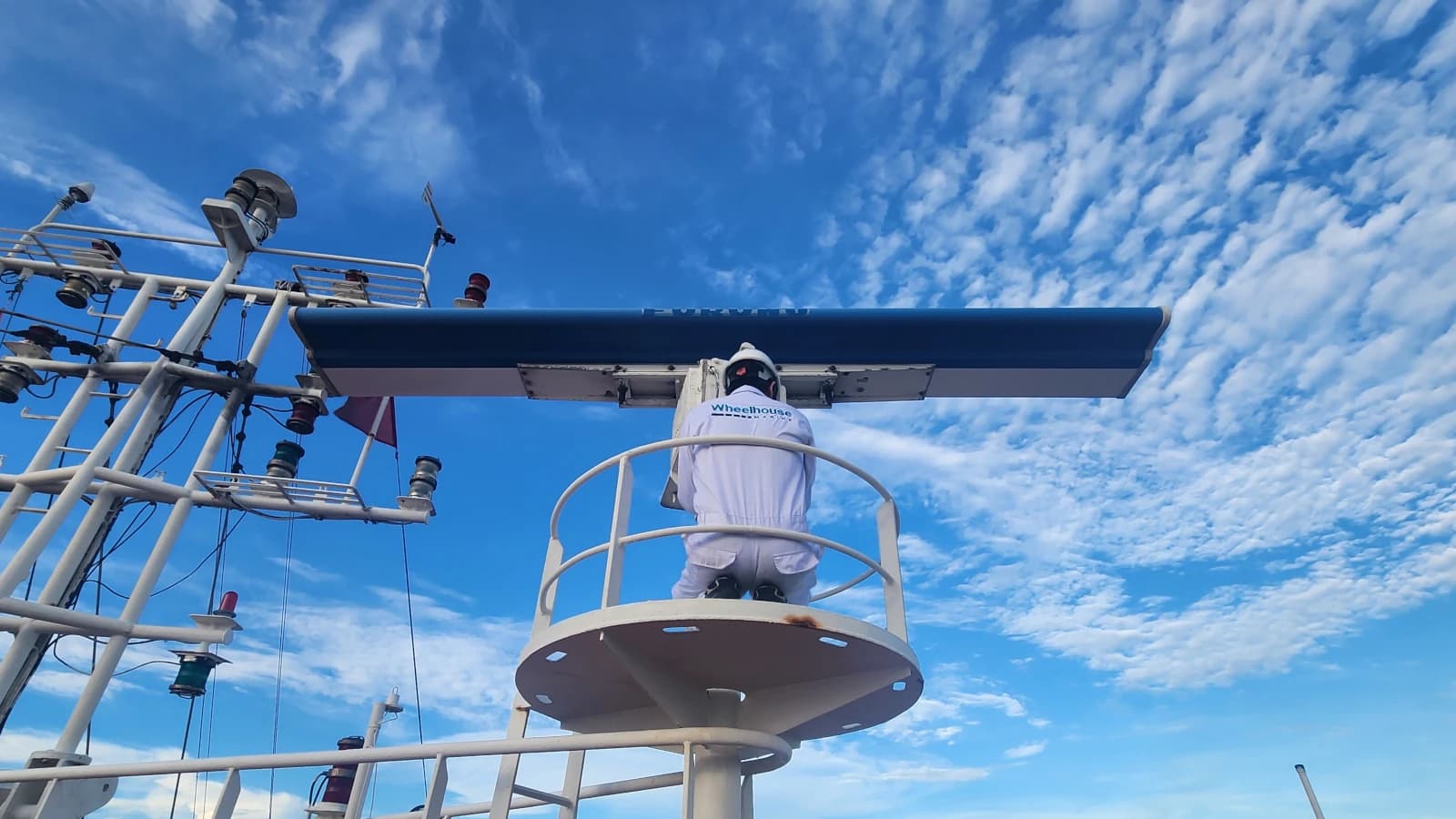
7. Partnering with Wheelhouse
Wheelhouse is committed to providing cutting-edge maritime RADAR solutions, including both Solid-State/Broadband and traditional Magnetron systems from leading brands like Furuno, JRC, Koden. We focus on technical solutions:
- Performance Optimization: Offering Antenna alignment services and technical parameter tuning to maximize target detection capability and minimize clutter interference in your specific operational area.
- ARPA Integration: Ensuring the ARPA system operates accurately with stable Kalman Filtering algorithms, providing reliable CPA/TCPA data for tactical decision-making.
We equip you with the tools necessary to maintain the highest level of situational awareness, thereby managing risks and complying with maritime safety regulations proactively.
To delve deeper into modern RADAR technologies, anti-clutter solutions, and technical support services, please visit our Solutions page.